Saturday, October 24, 2015
Knife Sheath
My brother's friend made a nice knife for himself, and he paid me to sharpen it. It was without a sheath so I made him one.
It initially had something like a convex grind. The edge was really blunt and just sharpening wouldn't have helped much. I decided to give it a Scandinavian grind. My coarsest stone is 6" long and 320 grit... it suffices to say we know each other well now, and a larger coarser stone is on its way. :')
Let me sharpen your things!
Tissue paper catching, but not quite hair-whittling sharp.
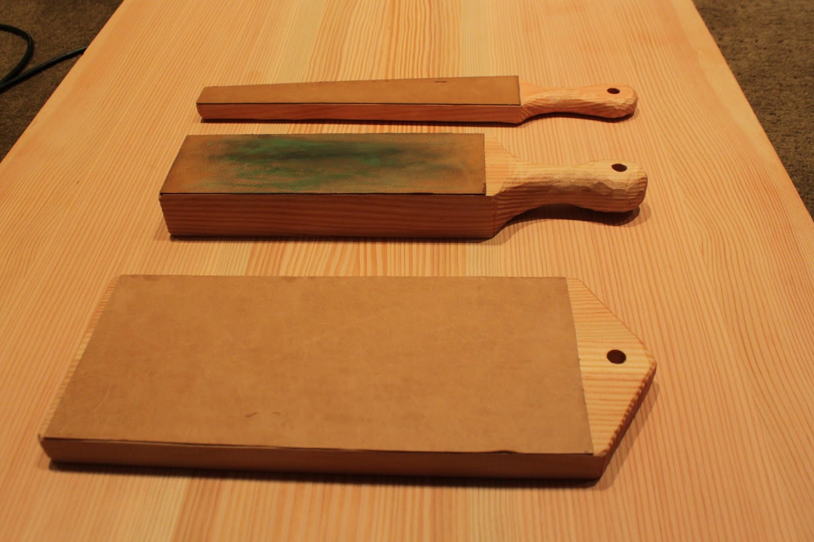
Made some strops with other leather scraps. I think the quality of leather is responsible for the scratches in the above picture. Or maybe it's because I didn't buy the electron-theory stropping aether. Maybe as business picks up...
I also sharpened this axe for the knifemaker. I tried to repair the sheath, which according to my brother, had gotten between the axe and a tree in the middle of the night.
The (saddle) stitches are just shy of the blade, buried in leather. I think they stand a chance.
Something nice and wooden will be posted next week.
Friday, October 9, 2015
Fan
Dad and I built a fan. He did most of the work. I designed it, ordered the parts, put the mechanical/electrical parts together, and mounted the motor. It has a nice quiet deep rumble like an airplane.
30" dia fan. 1725 RPM, 3/4 hp Baldor motor wired to 110 v. 7/8" fully keyed drive shaft on SKF mounted bearings. Overall width and height is 36".
It's not entirely finished; it will get wire mesh on the front and back for safety.
Thursday, October 8, 2015
Wooden Spooden
I got a Mora 163 hook knife for my birthday. Above is the second spoon I've made of old cherry. Making them is trance inducing, a little tricky.
Here's the first one I made:
I thought it was nice at first, but now it looks bulbous and awkward
compared to the second one. I've been eating with it and it does deliver
food to my face without issue!
I had a go at a cedar bowl too. The hook knife really isn't the tool for the job, and the cedar isn't really the wood for the job. I found it checking about a day in, so I cut the program budget and we left it like this:
With a hearty German breakfast:
Here are the tools. Intuition says the knife on the right is a bit long, but it's actually nice. Lots of reach, takes a long time to get dull. A little perilous, but no worse than the double (triple?) edged hook knife. I'm relieved every time I set the hook knife down and count all nine fingers.
More spoons to come, I am sure. Email me if your soup fork just isn't working out; I might be able to help.
Monday, September 28, 2015
Taig Milling
I needed to
The part is for an electronic leadscrew for the lathe. Here's a CAD sketch as messy as my workbench:
Friday, September 11, 2015
Begleri Beads
For a friend who is good with tops, yo-yo's, etc.
I can't take much credit for this fan since Dad did 95% of the work. It's coming along; I took some pictures after I affixed the struts and installed the mechanical parts. It looks out of a different time. Louvers, inlet screen, fan duct, and motor mount are in progress.
Here is a whistle I whittled out of elderberry (?) stalk. The inside is like sponge so I just cleaned it out with another stick. It worked when it was wet; I knew it would stop working when it dried out and shrunk. I have some more stalk drying out so I can make a long-term whistle... or maybe a blowgun.
The tube can be all sorts of things. Probably the most elegant one is made of willow as Ben Orford shows. There aren't many willows here though. Here is the recipe. The plugs are just round wood of some kind.
Saturday, September 5, 2015
Brass Handles
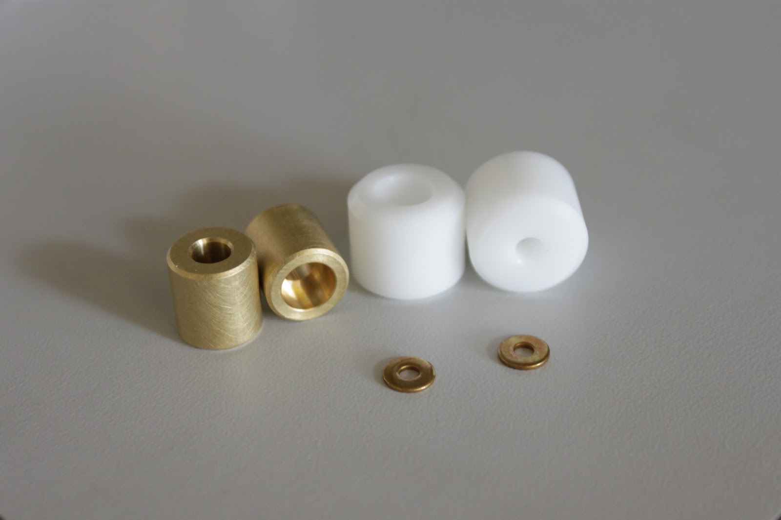
Here are four of eight brass handles I made for Dad to put on furniture. The 'knobs' are 3/4" diameter by 3/4" tall. Overall width is about 3 1/2". I also made eight handle-less knobs of the same dimensions.
Four months earlier:
From a previous post:
I'm rebuilding an old Craftsman power hacksaw. Taking my operation right into The Industrial Age.
Dad put the wide format box joint jig to good use. He's building a 34" square fan for us, which I designed. By "designed" I mean "ordered the parts for and scribbled out wooden connector pieces out in DaveCAD2000 Trial Version."
Fingers are 3/4" square. Forgot how deep the box is but feel free to count. It's big. Size reference is an ASME standard size LC-118-B bottle of C3H8O for those that counted the fingers.
Monday, August 24, 2015
Manual Tube Cope Pattern Making
I've figured out a method for generating 2D tube coping patterns without math, a printer, or a computer. I'm sure this method was taught decades ago, but it seems relatively unknown now. I think it can be useful to other people without tube notching equipment. It will probably seem like an overly complex and tedious process, and I suspect it would be for many people. That said, I find I can manually make patterns faster than I can with a computer.
It can be done most accurately and versatilely with a drafting table/machine, but here I'll show how to do it "in the field" with a sheet of paper, a pencil, and the tubes to be joined. The concept can be expanded to 3+ tube intersections and complex tube/shape profiles such as aero tube or rectangle tube. I'm leaving that out here; I figure if you can understand what's to follow you should be able to figure out how to make coping patterns for the wildest airplane fuselage. Otherwise, I can give you some pointers if you email me.
First, wrap your blank paper around the tube to be coped ("coped tube") and mark the circumference to the edge of the paper:
Unwrap:
Divide circumference into eight, sixteen, or any number divisible by four. More divisions yield greater accuracy and more potential for mistakes. If you divide into eight or sixteen, you can do it just by folding the page. Fold left corner to mark. Then fold left corner and mark to first dividing fold... keep dividing till you are content. Eight divisions is plenty for <3" diameter tube.
Trace your coped tube profile over the center line, towards the bottom. If you want the tube to be chamfered around the cope for welding, trace/draw the inside diameter. If you want to end up with a maximum-surface-contact fit, trace the outside diameter. You can use a compass, or just trace the tube directly by centering the end over the line. I have shortened the division lines for clarity:
If the target tube is smaller in diameter than the coped tube, the edges of the coped tube will shoot off to infinity unless we constrain them with a line. In that case, you draw horizontal lines out from the widest point of the target tube as shown in the example below. The target tube is an oval, shown in maroon. The constraining lines are red.
To business. Draw from 0 deg. on coped tube straight up to target tube, and follow that intersection horizontally over to 0 deg vertical division. Place tick there (blue dot):
See where this is going? Keep following the circle around...
Making these 'ghost' divisions is critical if there are abrupt changes in the target tube profile; the difference between a perfect fit and potentially a scrapped tube. I will illustrate this with the oval tube example from earlier, at the end of the round tube tutorial.
We now have the dots plotted to make a 90 degree tube cope. For our example, we want a 55 degree included angle, like this, but coped better:
We are about to repeat the target tube tracing routine, BUT this time the target line is 90 degrees out of phase so our references on the cope tube are rotated 90 deg. Another way to think of it is that instead of viewing the target tube end-on, we are viewing it side-on: you would rotate the tubes 90 deg. to switch between views. Also, instead of plotting points from the baseline, we plot them from the top of the existing points. In other words, we add them to the first plot. Here we go:
Full 360 deg.:
The mirrored point is to aid in drawing the continuous connector line, the interpolation if you will. Most tube copes are symmetrical and you can use this to your advantage. To mirror points on regular paper, just fold along the line of symmetry, hold up to the light, and plot your point. On thicker materials, dividers are your friend.
Let's connect the dots smoothly, see what we've got:
Of course, the proof is in the pudding... it feels wrong to print this out, since the whole point of the tutorial is to show how to cope tubes free of a printer/computer, but here we are:
My water bottle is a touch large in diameter for the pattern, but it's a very close fit regardless.
That's how it's done!
Now, the oval example demonstrates an important note:
These leaders point at abrupt changes in the target tube. These must be transferred to the cope tube, and 'ghost' divisions must be made or you will have lots of extra material removal to do:
The full 360 deg. works out to this:
That's all, folks-
It can be done most accurately and versatilely with a drafting table/machine, but here I'll show how to do it "in the field" with a sheet of paper, a pencil, and the tubes to be joined. The concept can be expanded to 3+ tube intersections and complex tube/shape profiles such as aero tube or rectangle tube. I'm leaving that out here; I figure if you can understand what's to follow you should be able to figure out how to make coping patterns for the wildest airplane fuselage. Otherwise, I can give you some pointers if you email me.
First, wrap your blank paper around the tube to be coped ("coped tube") and mark the circumference to the edge of the paper:
Unwrap:
Divide circumference into eight, sixteen, or any number divisible by four. More divisions yield greater accuracy and more potential for mistakes. If you divide into eight or sixteen, you can do it just by folding the page. Fold left corner to mark. Then fold left corner and mark to first dividing fold... keep dividing till you are content. Eight divisions is plenty for <3" diameter tube.
Trace your coped tube profile over the center line, towards the bottom. If you want the tube to be chamfered around the cope for welding, trace/draw the inside diameter. If you want to end up with a maximum-surface-contact fit, trace the outside diameter. You can use a compass, or just trace the tube directly by centering the end over the line. I have shortened the division lines for clarity:
Draw a baseline for your tube cope. If it is going to take up a lot of the tube (e.g. steep intersection), it will also take up a lot of the page, and the baseline should be drawn lower on the page to leave room:
Divide the coped tube profile into equal radial segments. Same division
as the circumference: in this case eight divisions. 360 degrees divided
by 8 in our case is 45 degrees. Draw these lines radiating from the center of the
coped tube profile. Conveniently, you can fold the paper diagonally to divide the
circle. You can also use dividers, a protractor, a ruler, or even
eyeball it.
Now, trace the profile of the non-coped tube ("target tube") above the first one. The
edge of the target tube profile should sit atop the baseline. If the axes of
the tubes line up, trace it that way. If there is a 10mm offset, trace
it 10mm off center. It might help to think that the coped tube is
'looking up at' the target tube.
If the target tube is smaller in diameter than the coped tube, the edges of the coped tube will shoot off to infinity unless we constrain them with a line. In that case, you draw horizontal lines out from the widest point of the target tube as shown in the example below. The target tube is an oval, shown in maroon. The constraining lines are red.
For clarity, I'll do a simpler cope now. The target tube will be the same diameter as the coped tube:
Numbers to aid in concept:
Now at 45 deg.:
See where this is going? Keep following the circle around...
The full 360 deg.
You will have to connect these blue dots into a continuous line. If you are uncertain about what the line does at a specific point, just make an approximate 'ghost' division and do the same thing you would with the other divisions:
We now have the dots plotted to make a 90 degree tube cope. For our example, we want a 55 degree included angle, like this, but coped better:
SO, we draw that angle onto our page:
Full 360 deg.:
The mirrored point is to aid in drawing the continuous connector line, the interpolation if you will. Most tube copes are symmetrical and you can use this to your advantage. To mirror points on regular paper, just fold along the line of symmetry, hold up to the light, and plot your point. On thicker materials, dividers are your friend.
Let's connect the dots smoothly, see what we've got:
Of course, the proof is in the pudding... it feels wrong to print this out, since the whole point of the tutorial is to show how to cope tubes free of a printer/computer, but here we are:
My water bottle is a touch large in diameter for the pattern, but it's a very close fit regardless.
That's how it's done!
Now, the oval example demonstrates an important note:
These leaders point at abrupt changes in the target tube. These must be transferred to the cope tube, and 'ghost' divisions must be made or you will have lots of extra material removal to do:
The full 360 deg. works out to this:
That's all, folks-
Subscribe to:
Posts (Atom)